Watteco IN'O
Wiring the device
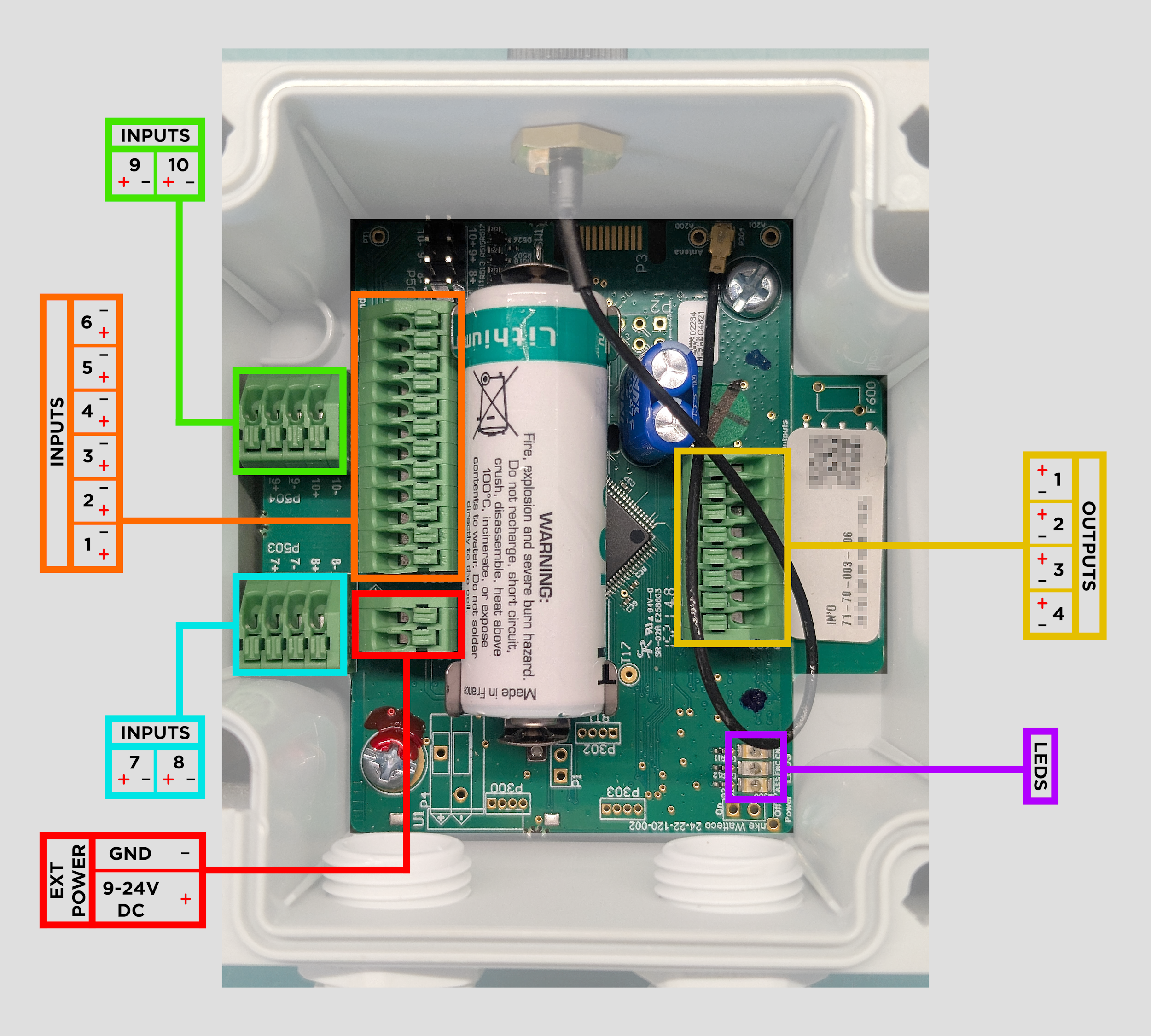
The IN'O features 10 digital inputs which can be driven either from a voltage in the range 0-30V DC, where 0V to 0.8V DC is a low state and 2.5V to 30V DC is a high state. Or, by joining the positive input to negative using a dry contact where contact closed is a low state and contact open is a high state. For example, if wiring a single voltage input, the positive wire would be connected to Input 1+ and the ground / common wire would be connected to Input 1-. The maximum driving rate for either input method is 100Hz. Refer to the diagram of terminals below for further wiring details.
The IN'O can either be powered by battery only, or externally by applying 9-24V DC to the external power contacts. In the event of external power loss the non-rechargeable battery will continue to power the device as long as it still has sufficient charge. The positive wire from the power supply would be connected to Ext Power + and the ground / common wire would be connected to Ext Power -.
All wires should pass through the product cable glands and stripped by 5-6mm prior to insertion in the corresponding terminals. The terminals are of the spring cage type: the actuator is pressed down using a small screwdriver while the stripped wire is carefully inserted fully into the corresponding opening ensuring there are no stray strands, then once the actuator is released the stripped wire end will be clamped in place.
Positioning the device
The device should be placed as high as possible, with the antenna pointed upwards, and the number of obstacles limited to reduce the affects of radio attenuation. In particular try to avoid placement adjacent to metal poles or mounting plates as these can severely limit the radio propagation to and from the device.
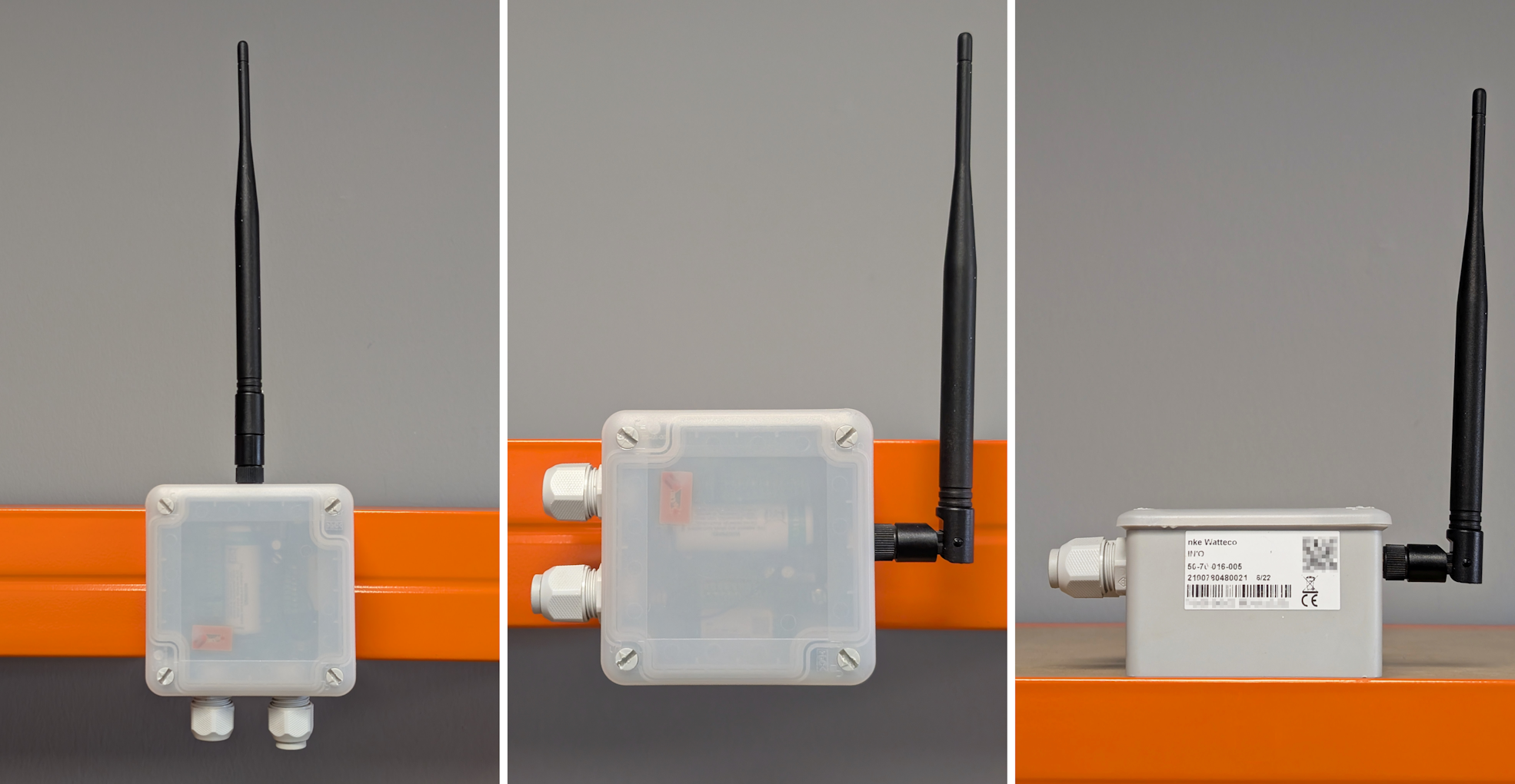
For further details on device mounting please refer to the included quick start guide; this is also available digitally from the manufacturer webpage
Switching the device on and off
The IN'O features a magnetically activated reed switch, the position of which is normally indicated by an "ILS" sticker on the side of the casing.
The IN'O also features status LEDs which are visible through the semi-transparent cover.
NOTE: The device should be left in its off state prior to associating with K-Cell, and switched on once the status in the Aquatics interface has changed to "Awaiting Device".
To switch the device on, hold a magnet against the casing at the reed switch position for > 1 second, during which the red LED should flash rapidly. Once the red LED has stopped flashing and the green LED has started flashing (short individual pulses 5 seconds apart) the magnet should be moved away from the casing. The device is now in the network searching mode. Once network association has completed successfully, the green LED should turn on steady for 3 seconds, then turn off. Start up is complete.
To switch the device off, hold a magnet against the casing at the reed switch position for > 5 seconds, during which the red LED should flash rapidly. Once the red LED changes to flashing 5 times over 3 seconds the magnet should be moved away from the casing. Shut down is complete.
Reassociating the Device
If the device needs to be reassociated for any reason (for example if the K-Cell is replaced) this can be achieved while the device is on by passing a magnet near the reed switch position (indicated by an "ILS" sticker on the side of the casing) three times in succession, following which the green led should start flashing (short individual pulses 5 seconds apart). The device is now in the network searching mode. Once network association has completed successfully, the green LED should turn on steady for 3 seconds, then turn off. Reassociation is complete.
For further details on device operation please refer to the manufacturer's documentation at https://support.nke-watteco.com/ino-2/>
K-Cell association
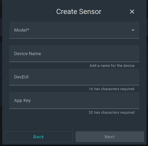
From the site/sensors page press the Add sensor button then:
- Select the Watteco Ino-2 sensor from the dropdown list.
- Optionally add a descriptive name or location e.g. Bilge pump
- Enter the DevEUI
- Enter the App Key
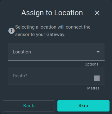
Next set the location on the site from the dropdown list and set the depth field to 0 meters and the Pressure to 1 atm then press next.
Set useful names and keys for the sensor data. Note that you can not edit the keys after creation. Press next.
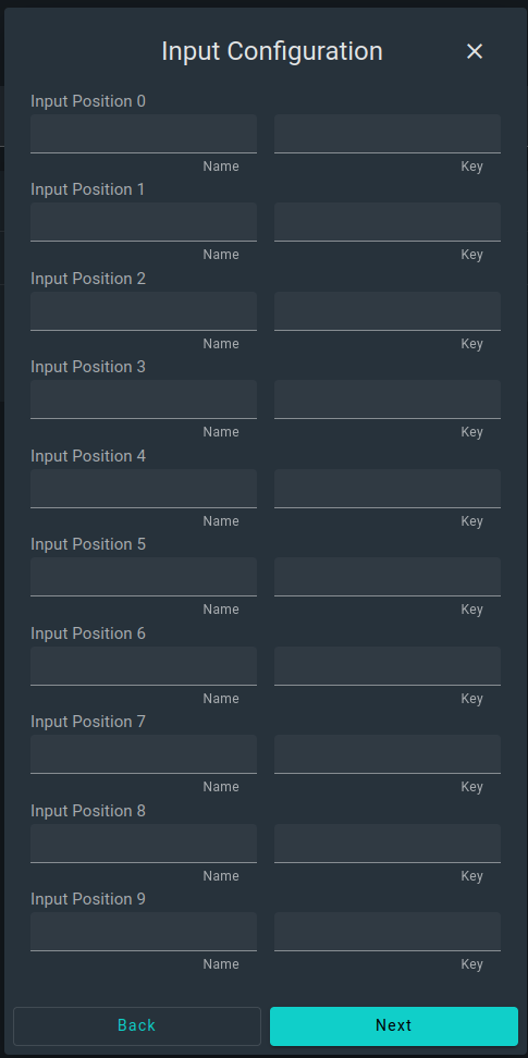
Populate the configuration page for each input you chose to enable.
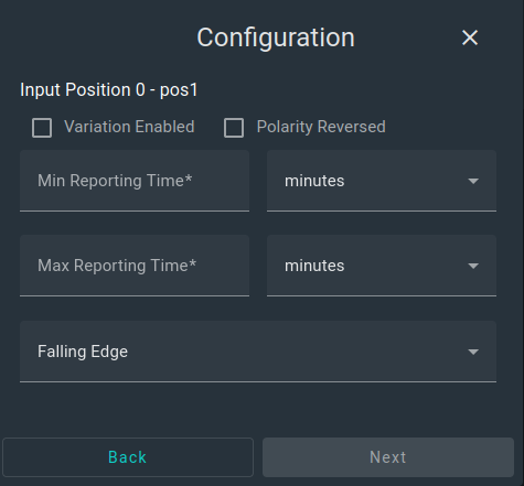
| Option | Usage | Recommended setting |
|---|---|---|
| Min reporting time | Minimum time between transmissions even if change detected | 60 seconds |
| Max reporting time | Maximum time to send data even if no change | 60 minutes |
| Variation enabled | Enable reporting of state changes of an input | True |
| Polarity reversed | Reversed signal polarity if selected | False |
| Edge selection | Edges which will be included in count (if used) | Both edges |
On the summary page press save to apply your settings and synchronise to the K-Cell.